Description
About the course
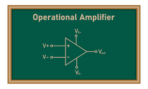
This course will introduce you to one of the most important components in Electronics, which is an Op-Amp. In this course, you will learn about the Op-Amps circuits and how an Op-Amp works as a difference amplifier. Also, you will learn about instrumentation amplifiers followed by understanding the bode plots which determine the frequency response of the Op-Amps. After that, you will learn about the application of Op-Amps in designing filters which are commonly known as high-pass, low-pass, band-pass and band reject filters. Next, you will learn about precision rectifiers, which also make use of Op-Amps followed by Schmitt Triggers. Finally, the course concludes with Sinusoidal oscillators.
Learning Outcomes
After completing this course, you will be able to:
- Understand the fundamentals and working of operational amplifiers.
- Understand the application of operational amplifiers in designing instrumentation amplifiers, filters, precision rectifiers, Schmitt triggers, and sinusoidal oscillators.
- Design your own amplifiers, rectifiers, and filters.
- Boost your hireability through innovative and independent learning.
Target Audience
The course can be taken by:
Students: All students who are pursuing professional graduate/post-graduate courses related to computer science and engineering or data science.
Teachers/Faculties: All computer science and engineering teachers/faculties.
Professionals: All working professionals from computer science / IT / Data Science domain.
Why learn Op-Amps?
Since the introduction of the first IC op amp, huge improvements have been made in both semiconductor processing and circuit design. For roughly 40 years, IC manufacturers have employed these improvements to design nearly ""ideal"" amplifiers. In the present world of precision amplifiers, small-signal designers concern themselves with critical factors such as low supply current, low offset, low noise, and low bias current. Significant improvements have been made in all aspects of process technology. These improvements allow amplifier design engineers to take the maximum performance and functionality from every technology. The demand for the design engineers has also increased due to these developments in the field of core electronics engineering and will continue to grow in the coming future.
Course Features
- 24X7 Access: You can view lectures as per your own convenience.
- Online lectures: 10 hours of online lectures with high-quality videos.
- Updated Quality content: Content is latest and gets updated regularly to meet the current industry demands.
Test Evaluation
Each lecture will have a quiz containing a set of multiple choice questions. Apart from that, there will be a final test based on multiple choice questions.
Your evaluation will include the overall scores achieved in each lecture quiz and the final test.
Certification
This course is free and it has no certificate.
Topics to be covered
- Module 01: Introduction to Op-amps
- What are Op-Amps?
- What is the equivalent circuit of an Op-Amp?
- What is the circuit of an Op-Amp in an Op-Amp (Linear region)?
- Module 02: Op-amp circuits-1
- How does Op-Amp operate in Linear region?
- How is OP-Amp implemented as an inverting amplifier?
- How to determine whether an Op-Amp circuit is inverting or non inverting?
- Module 03: Op-amp circuits-2
- What is a non-inverting amplifier and what are the loading effects?
- What is the input resistance of an Op-Amp and a non-inverting amplifier?
- What is the Output resistance in case of an Op-Amp buffer?
- Module 04: Op-amp circuits-3
- What are the different working examples of an Op-Amp and how it is implemented as a Summer?
- How are the resistance values chosen?
- Module 05: Difference amplifier
- What are common mode and differential mode voltages and what is Common Mode Rejection Ration (CMRR)?
- What is a Difference Amplifier and how it works?
- Module 06: Instrumentation amplifier-1
- What is the working of a difference amplifier?
- What is the effect of resistance mismatch on common mode component and what is the circuit for Instrumentation amplifier?
- Module 07: Instrumentation amplifier-2
- How instrumentation amplifier works and what is its common mode rejection performance?
- How current to voltage conversion is done?
- How is Op-Amp implemented as an integrator?
- Module 08: Op-amp nonidealities-1
- What are the non-idealities of Op-Amp and what is the offset voltage in practical Op-Amp?
- What is the effect of Offset voltage on an inverting amplifier and integrator?
- What is the input bias current?
- Module 09: Op-amp nonidealities-2
- What is the effect of bias currents on an inverting amplifier?
- What is the effect of bias currents on an integrator?
- What are filters and their examples?
- Module 10: Bode plots-1
- What is deciBel (dB) and how it is calculated?
- What is Bode plot for a simple transfer function?
- What are the variations in magnitude and phase of transfer function?
- Module 11: Bode plots-2
- How is the Bode plot constructed for a simple circuit?
- What is the contribution of a pole in magnitude and phase Bode plots?
- What is the contribution of a zero in magnitude and phase Bode plots?
- What is the contribution of K (constant), s and s2?
- Module 12: Bode plots-3
- How to construct a bode plot by combining different terms in the transfer function?
- How to compare the results of Bode approximation with an actual magnitude and phase plots?
- How to compute the transfer function using SEQUEL GUI?
- Module 13: Op-amp filters
- What are the different practical filter circuit and what are High Pass and Low pass filters?
- What are active filters and their examples?
- What are a graphic equalizer and its example?
- Module 14: Simulation of op-amp filter
- How to simulate an Op-Amp filter and plot the magnitude of the transfer function with frequency?
- Module 15: Precision rectifiers-1
- What is a Half wave rectifier?
- What is the application of a super diode or the half-wave precision rectifier?
- How to use a peak detector for AM demodulation?
- Module 16: Precision rectifiers-2
- What is a precision clipping circuit?
- What is a precision clamping circuit?
- What is the speed limit of a half wave rectifier based on the super diode?
- Module 17: Precision rectifiers-3
- What is an improved Half-wave precision recifier?
- What is a Full-wave precision rectifier?
- What is the meaning of Wave shaping?
- What is the spectrum of input and output voltages?
- Module 18: Simulation of the triangle-to-sine converter
- What is a triangle-to-sine wave converter?
- How to simulate triangle-to-sine wave converter circuit?
- Module 19: Schmitt triggers-1
- What is a positive feedback in an inverting and non-inverting amplifier?
- What is inverting Schmitt trigger?
- What is non-inverting Schmitt trigger?
- Module 20: Schmitt triggers-2
- What is a comparator and how it works?
- How is Schmitt trigger used for waveform generation?
- Module 21: Schmitt triggers-3
- How Schmitt trigger circuit allows threshold voltages to be shifted using a reference voltage?
- What are sinusoidal oscillators?
- What is the example of a gain limiting network?
- Module 22: Sinusoidal oscillators-1
- What is a wein bridge oscillator?
- What is a phase shift oscillator?
- Module 23: Sinusoidal oscillators-2
- How is gain limiting network used for amplitude control?
- What are the frequency response of an Inverting amplifier and a realistic Op-Amp 741?
- Working with Op-Amps Final Quiz
Reviews
There are no reviews yet.